

How to Properly Choose Low-Voltage AC Contactors
01 Preface
Low-voltage AC contactors are one of the most commonly used electrical components in power control circuits, and many electrical professionals are familiar with them. However, choosing the right type of contactor for specific applications can still be confusing. Today, we will explain how to select low-voltage AC contactors correctly by examining their structure, principles, and functions.
02 Overview of Structure and Principles
A low-voltage AC contactor is an electrical device used to automatically connect or disconnect circuits under load. It can frequently make or break AC and DC circuits, enable remote control, and cooperate with relays to achieve timing operations, interlocking, quantitative control, under-voltage, and over-voltage protection.
The primary control target of AC contactors is motors, but they can also control other loads, such as heaters, lighting devices, and capacitors. AC contactors feature large control capacity, strong overload resistance, long service life, and economic simplicity, making them widely used in power drive and automatic control circuits.
An AC contactor mainly consists of four parts:
Electromagnetic system: The core operating part, composed of a coil, an iron core (static core), and an armature (movable core).
Contact system: Includes main contacts and auxiliary contacts.
Arc extinguishing device: Suppresses electrical arcs generated during contact opening.
Auxiliary components: Additional elements for control and signaling.
When energized, the coil creates an electromagnetic force that causes the armature to move, closing the movable and static contacts, thus connecting the main circuit. Upon de-energization, the contacts open under the action of return springs and other forces. Arcing occurs at the moment of contact separation, and an arc-extinguishing device suppresses it.
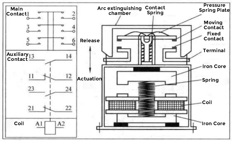
Figure 1 Model diagram of AC contactor
In Figure 1, we see that the main contacts of the contactor belong to a bridge structure with double breakpoints. When the coil is charged, the armature runs downward driving the movable contact to slap on the static contact. Since the currents in the moving and static contacts are in opposite directions, the currents generate electric repulsion between them. The pressure spring plate of the movable contact is used to eliminate the effect of electric repulsion. When the coil is de-energised, the moving and static main contacts return to the released position by the combined action of the buffer spring, the contact spring and the electrodynamic repulsive force. At the moment when the main contacts open, an arc will be generated between the moving and static contacts, and the purpose of the arc extinguishing shield is to extinguish the arc. AC contactor rated connecting capacity is the value of the current that can be connected under the specified conditions, and at this time the contacts do not melt weld, there is no obvious burns, and there is no strong flying arc. The rated breaking capacity of the contactor is the value of the current that can be broken by the contactor under the specified conditions without the contacts being burnt to the extent that they cannot be operated and without strong flying arcs. The electrical life of an AC contactor is a parameter that indicates the ability of the contactor to resist electrical wear and is expressed in terms of the number of on-off cycles under load. Measuring the electrical life of an AC contactor does not allow for servicing or replacement of parts. Figure 1, left, shows the primary contact at the top, the secondary contact in the middle and the drive coil at the bottom.
03 Classification
- By Number of Main Contacts:
Single-pole, double-pole, three-pole, four-pole, and five-pole contactors.
Single-pole contactors are mainly used for single-phase loads, such as lighting circuits and welding machines and other loads; bipolar contactors are used in the rotor circuit of wound rotor asynchronous motors, and are used to short the starting winding when starting the motor; three-pole contactors are used for three-phase motor control; four-pole contactors are used in three-phase, four-wire lighting circuits, as well as two-speed motor; five-pole contactors are used to form an autotransformer starter circuit for the motor, and are also Five-pole contactors are used to form motor autotransformer starting circuits and also to control two-speed motor control circuits to change the winding connection.
- By Arc-Extinguishing Medium:
Air-insulated contactors: For general loads.
Vacuum contactors: For special environments like coal mines, petrochemicals, or voltages of 660V and 1140V.
- By Contact Type:
Contact-based contactors: Commonly used.
Contactless contactors: Use thyristors for switching, suitable for flammable and explosive environments.
04 Basic Technical Parameters
- Rated Voltage:
The voltage at which the contactor's main contacts operate, typically equal to the load’s operating voltage, e.g. 220~230V、230~240V、380~400V and 400~415V - Rated Current:
The maximum current the contacts can carry. Common ratings range from 9A to 2000A. - Making and Breaking Capacity:
Contactor connecting and breaking capacity including the maximum connecting current and maximum breaking current two indicators. Maximum on-current is the contact closure and will not cause the maximum current value of the contact welding, the maximum breaking current is the maximum current that can reliably extinguish the arc when the contact is broken. General breaking capacity is 5 to 10 times the rated current. Breaking capacity is related to the voltage level, the higher the voltage level, the smaller the breaking capacity. For example, AC contactors working under AC-2, AC-3 and AC-4 should be able to meet the overcurrent of 8 times of the maximum rated working current of AC-3 category. 630A and the following contactor carrying time is 10s, and the carrying time of 630A and above contactors will be slightly shortened. The categories of use and on-off conditions for AC contactors are shown in the table below
-
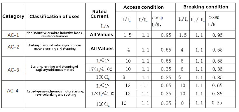
Table 1 Classes of use and on-off conditions for AC contactors
In Table 1
I - turn-on current;
In - rated current;
Ib - breaking current;
U - voltage before switching on
Un - rated voltage;
Ur--Recovery voltage
Note:
- The error of cosφ is ±0.05 and the error of L/R is ±15%;
- The minimum value of I or Ib is 1000A;
- The minimum value of Ib is 800A.
- The minimum value of I is 1200A.
(4) Motion value
The action value of the contactor is divided into suction voltage and release voltage. Suction voltage refers to the minimum voltage at which the coil voltage is slowly increased to make the AC contactor close before the contactor closes; release voltage refers to the maximum voltage at which the coil voltage is slowly decreased to make the AC contactor release. It is generally stipulated that the suction voltage should not be lower than 85 per cent of the rated coil voltage value, and the release voltage should not be higher than 70 per cent of the rated coil voltage value.
(5) Operating frequencyThe operating frequency of a contactor refers to the maximum value of the permissible number of operations per hourThe permissible number of operations per hour can be divided into: 1/h, 3/h, 12/h, 30/h, 120/h, 300/h, 600/h, 1200/h and 3000/h.The operating frequency influences the electrical life of the AC contactor, and also influences the temperature rise of the AC contactor coil.
(6) Work system contactors have four kinds of work system, respectively, eight-hour work system, uninterrupted work system, intermittent cycle work system and short-time work system. Eight hours of work is the basic system of contactors, the agreed parameters of the heating current is determined according to eight hours of work; uninterrupted work system is much more severe than eight hours of work, the contacts of the contactor is prone to oxidation and the coil is prone to overheating. In the uninterrupted working system, the contactor needs to reduce the use of capacity; intermittent cycle working system of the load rate of 15 per cent, 25 per cent, 40 per cent and 60 per cent of the standard value respectively; short-time working system under the contact of the standard value of the time of energisation of 10min, 30min, 60min and 90min and so on four kinds.
(7) Category of use
There are four standard use categories for contactors, AC-1, AC-2, AC-3, and AC-4. AC-3 is for direct motor starting and operation, while AC-4 is for reversible motor starting, reverse braking, and electric power.
(8) Mechanical and electrical life of the mechanical life of the contactor is defined as the number of unloaded cyclic operations it can withstand before normal maintenance and replacement of mechanical parts, and the electrical life of the contactor is defined as the number of times it can be operated with a load without repair or replacement of parts under standard conditions of use. Under conditions not otherwise specified, the number of times the electrical life of a contactor in the AC-3 use category shall be not less than 1/20th of the number of times the corresponding mechanical life.
05 Control Circuit Parameters
Suction coil rated voltage: the value of the voltage applied to the coil during normal operation of the contactor.
The voltage applied to the coil when the AC contactor is working is often the same as the main circuit voltage, but it may not be the same, and sometimes a DC power supply may be used. This is determined by site conditions and design.
The voltages loaded on the AC contactor coils are standard values, see Table 2.
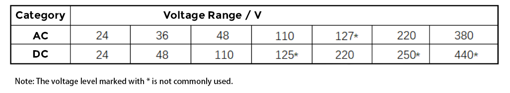
Table 2 Standard data for voltage loaded on AC contactor coils
06 Selection of Low-Voltage AC Contactors
When selecting an AC contactor, the following principles apply:
- Determine the number of poles required.
- Specify main circuit parameters, including rated voltage, current, and overload capability.
- Choose appropriate control circuit parameters.
- Ensure the contactor’s electrical life matches its usage category.
- For the contactor with the motor, it is necessary to consider the operation of the motor separately.
① For one-way operation of the motor, such as fans, pumps and other loads, AC contactors can be selected according to the AC-3 category; ② For reversible motors, its reverse operation, pointing and reverse braking current can be up to 8 times the rated current or more. Therefore, AC contactor should be selected according to AC-4 category. When the power of the motor is not more than 630kW, the contactor should be able to withstand 8 times the rated current for at least 10s. ③For general motors, the working current is less than the rated current, although the motor starting current can be up to 4 to 8.4 times the rated current, but the time is short, and the erosion of the main contacts of the contactor is not very significant, so the choice of the rated current of the AC contactor is more than 1.25 times of the rated current of the motor. 1.25 times of the rated current of the motor. ④Wire-wound rotor asynchronous motor on current and breaking current are 2.5 times the rated current, can choose to use the category of AC-2 AC contactor.
- For heating equipment, select contactors in the AC-1 usage category with a current rating at least 1.2 times the heating load current.
- For capacitor switching, due to inrush currents reaching 1.43 times the rated current, choose contactors rated for 1.5 times the capacitor current.
07 Conclusion
When selecting a low-voltage AC contactor, consider control methods, operating environments, and cost factors to ensure safety, suitability, and economic efficiency. Comprehensive analysis and careful selection are essential to ensure stable and reliable operation of electrical control systems.
